
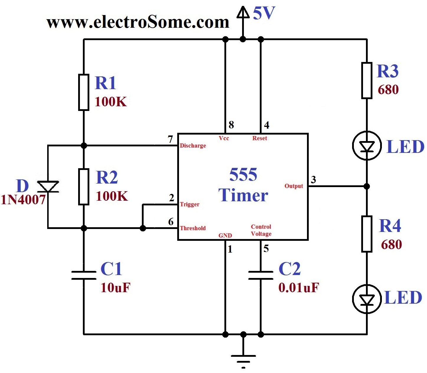
555 Timer Basics Astable Mode
A timer switch or timer circuit is a timer to control any electronic switches or circuits by a timing mechanism. Here, the timer is a very simple circuit, working by using just one or a pair of transistors. this circuit serves its purpose of time delays operation of a device. The timer circuit is made with a number of different schematics which.
Simple 2 minute Timer Circuit for your DIY Digital Lab
Two Step Sequential Timer. The above circuit can be modified to produce a two step sequential delay generator. This circuit was requested by one of the avid readers of this blog, Mr.Marco. A simple delay OFF alarm circuit is shown in the following diagram. The circuit was requested by Dmats. The following circuit was requested by Fastshack3
Simple Timer Circuits using IC 555 Adjustable from 1 to 10 minutes
The 555 timer IC is a very cheap, popular and useful precision timing device which can act as either a simple timer to generate single pulses or long time delays, or as a relaxation oscillator producing a string of stabilised waveforms of varying duty cycles from 50 to 100%. The 555 timer chip is extremely robust and stable 8-pin device that.
Simple Delay Timer Circuits Explained Homemade Circuit Projects
But Did You Check eBay? Check Out Circuit Timer On eBay. Fast and Free Shipping On Many Items You Love On eBay.
Submersible Pumpset Timer Circuit
Tutorial 2: Transistor Timer Circuit. Created on: 27 July 2012. Updated on: 12 January 2023. A transistor timer circuit for beginners in electronics that uses a single transistor. When the circuit is powered by a 9V battery, the LED switches on. A switch (or link on the breadboard) is closed to start the timer, causing the LED to switch off for.
Simple long duration timer
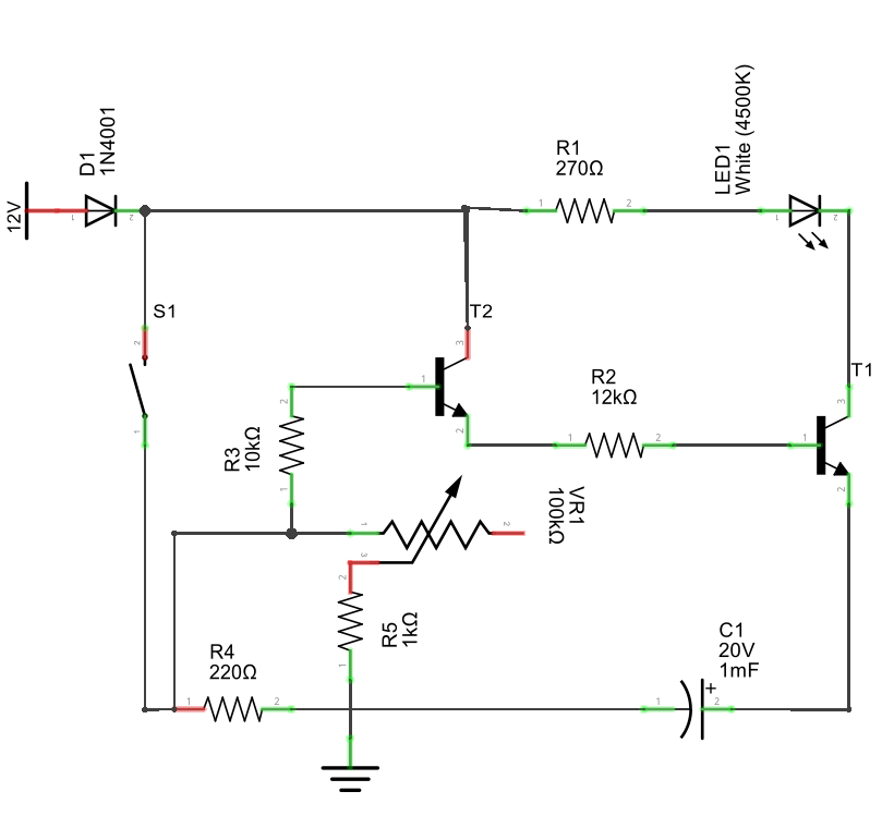
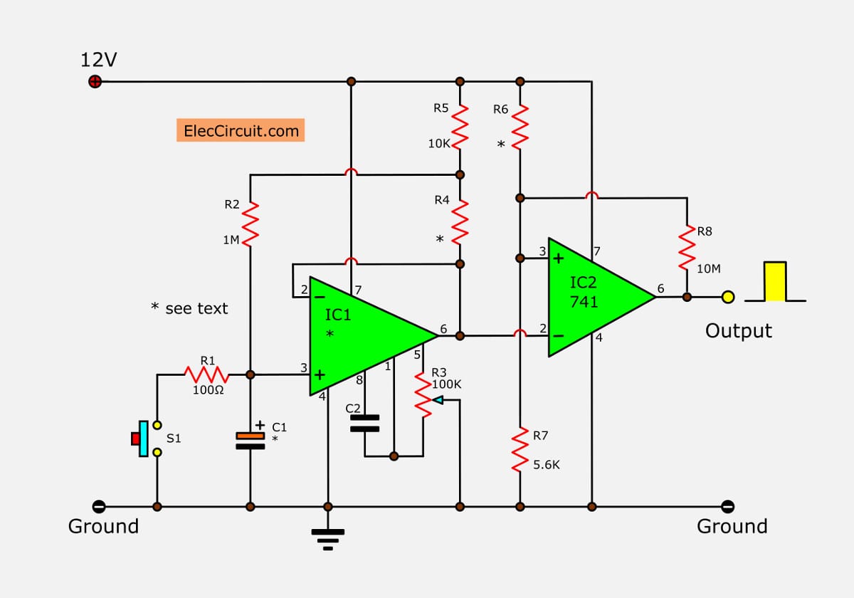
1 Minute Porch Light Timer. This 8th circuit shows simple porch light timer circuit that can be activated for a minute only during night time. During day time the LDR resistance becomes low which keeps its junction with R5 high. Due to this, pressing S1 has no effect on pin 2 of the IC. However, when darkness falls, LDR resistance goes infinite.
How to Make an Industrial Delay Timer Circuit Homemade Circuit Projects
555 Circuits Part 1 - The Fastest 555 Oscillator. By varying the value of either R or C the 555 astable multivibrator circuit can be made to oscillate at any desired output frequency. But what is the maximum frequency of oscillations we can produce from a single 555 timer chip. To get the 555 to operate at its highest frequency in this 555.
Simple Delay Timer Circuits Explained Homemade Circuit Projects
555 Timer Circuits. The 555 Timer IC is a popular 8-pin Integrated circuit chip that can be used in a variety of timing and pulse generation applications. The IC can operate in three different modes such as Astable, Monotstable and Bistable, because of which it can be adapted into many types of circuit designs like time delay circuits, pulse.
How to make delay timer circuit ,diy easy delay circuit YouTube
Simple 555 Timer Circuits & Projects. March 18, 2017. By Anusha. 555 timer is an industrial standard IC existing from early days of IC. Its name is derived from three 5K ohm resistors ,connected in series used in it.The timer IC can produce required waveform accurately. 555 timer was first introduced by signetics corporation in 1971 as SE555/NE555.
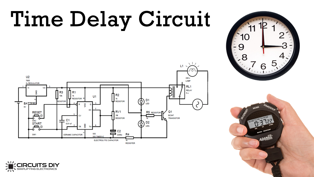
Simple Time Delay Circuit using 555 Timer
Here i am going to explain different ways of building adjustable timer circuits. However, these methods are cost ineffective.Three circuits are explained here are 1)Simple adjustable timer using 555 IC,2)A cyclic on/off timer using 555 IC,3)Adjustable timer using arduino. (40+ Simple 555 Timer Circuits & Projects)
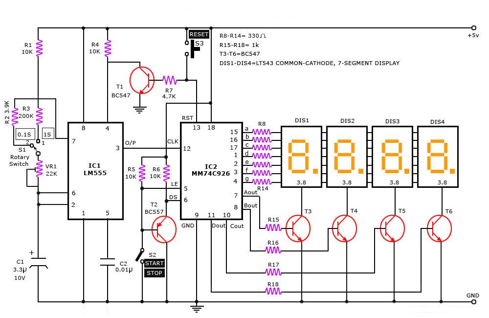
Digital Stop Watch Simple Projects
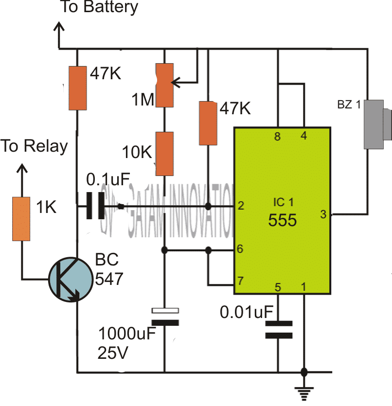
So to build 1 minute (60 seconds) timer we need resistor of value 55k ohm and capacitor of 1000uF: 1.1*55k*1000uF. (1.1*55*1000*1000)/1000000 = 60.5 ~ 60 seconds. A variable resistor of 1M is used here and set on 55k ohm (measured by multimeter). We can easily calculate the resistor value for 5 minute, 10 minute and 15 minute timer circuit:
555 timer circuit Page 4 Other Circuits Next.gr
¡Precios increíbles y alta calidad aquí en Temu. Envío gratuito en todos los pedidos. ¡Solo hoy, disfruta de todas las categorías hasta un 90% de descuento en tu compra.

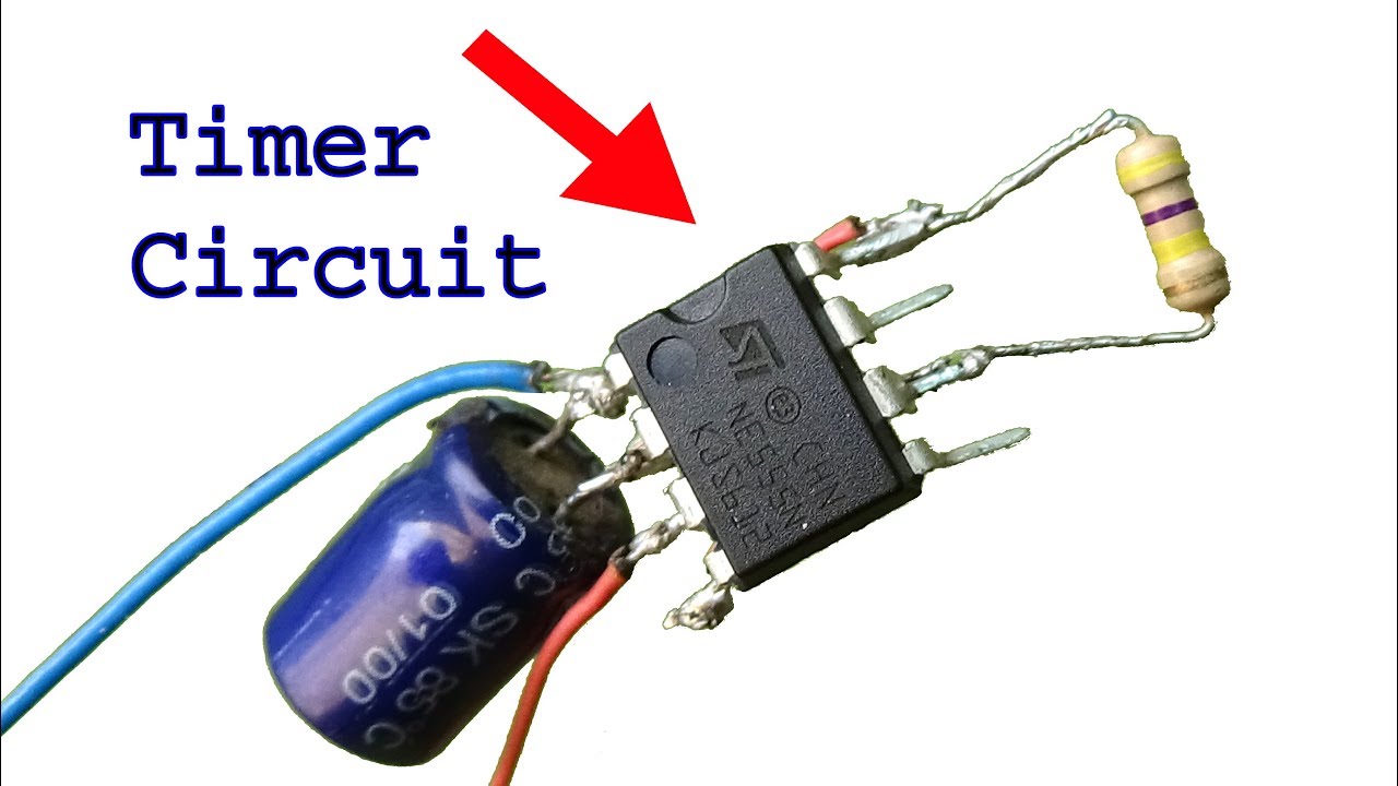
TIMER CIRCUIT how to make simple timer circuit using one transistor YouTube
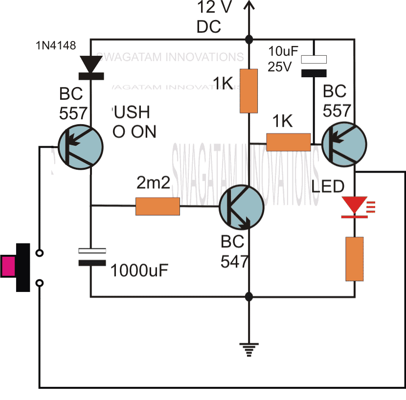
Timer Circuit with Relay Switching. If you are wondering how the above simple timer circuits could be used for triggering a high power load through relay switching, then the following diagram will help you to implement the same by attaching a simple relay stage with the shown designs: Parts List. All resistors are 1/4 watt 5%. R1, R4 = 4K7, R2.
Simple 5 to 20 Minute Delay Timer Circuit Circuit Diagram Centre
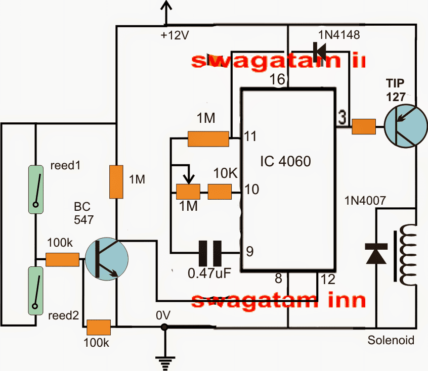
Simple Programmable Timer Circuit. Last Updated on January 2, 2024 by Swagatam 452 Comments. This programmable timer can be used for switching a load ON and OFF with two sets of time delays, which are programmable from 2 seconds to 24 hours independently. The delay timings are adjustable according to the users personal specs.
Timer Circuits with Auto Pause and Memory During Power Failures Homemade Circuit Projects
in this video, I will show you how to make a time circuit using a transistorBuy Electronic Component From Here:- https://www.electronicspices.com/If u really.

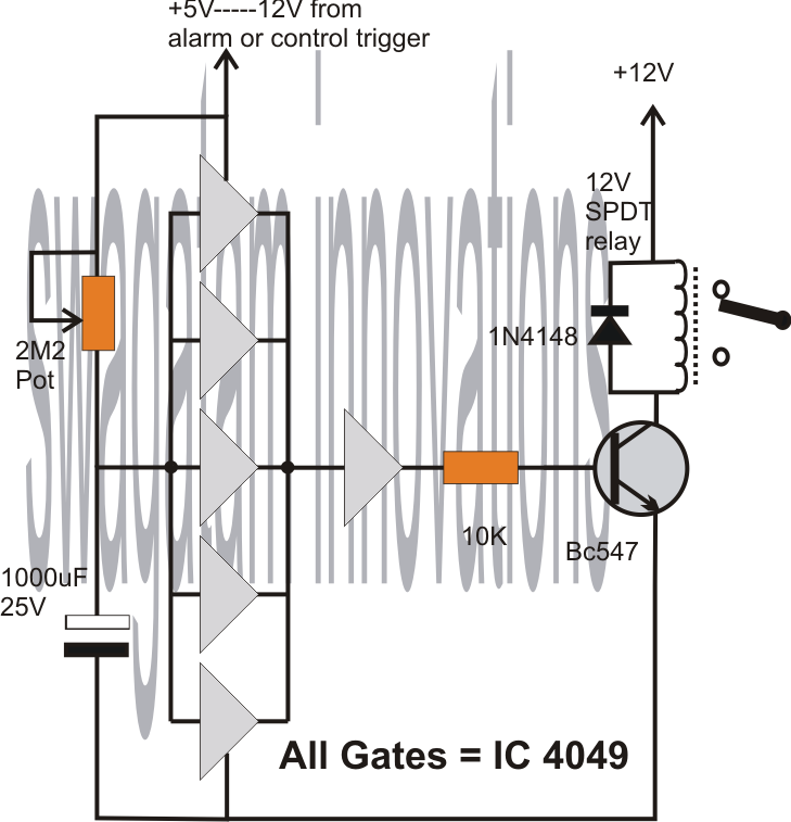
Simple Delay Timer Circuits Explained
In astable mode, the output from the 555 timer is a continuous pulse waveform of a specific frequency that depends on the values of the two resistors (R A and R B) and capacitor (C) used in the circuit (fig 1) according to the equation below.Astable mode is closely related to monostable mode (discussed in step 2), you can see that the schematic is nearly the same.